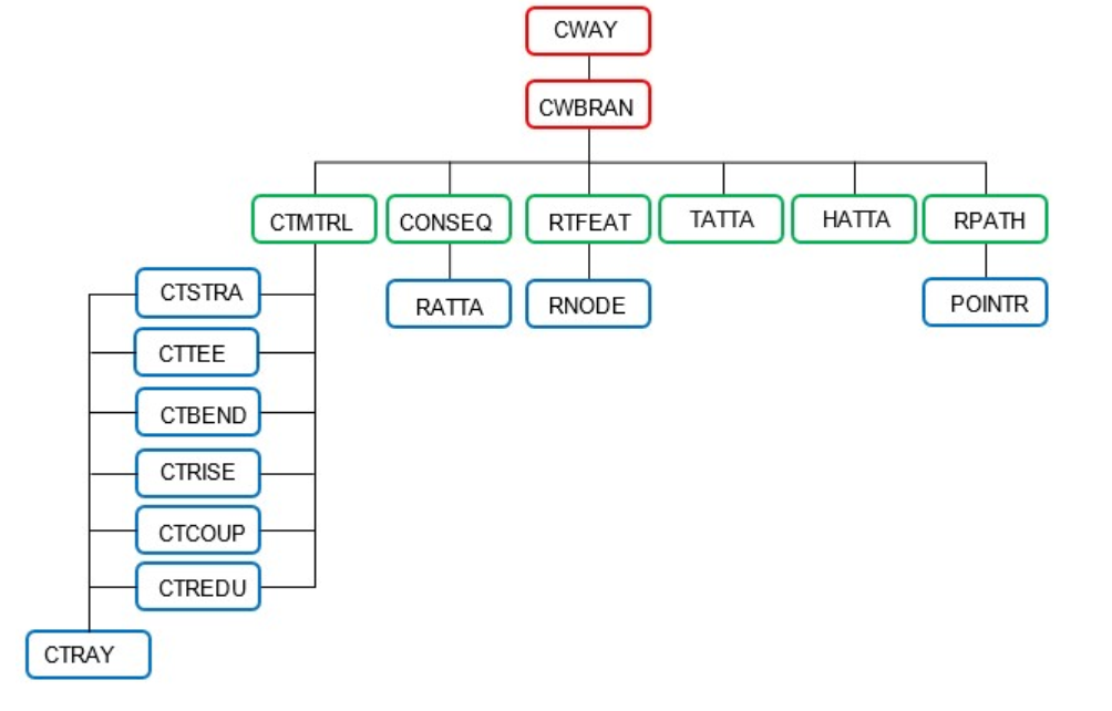
Both modules are currently available and accessible.
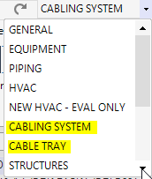
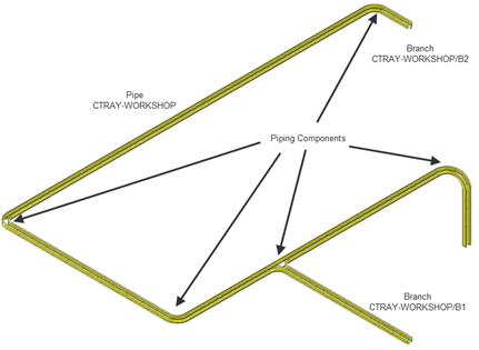
The CABLE TRAY module is the legacy solution inherited from PDMS. It enables the creation of cable tray and conduit representations within the 3D model using the hierarchy:
PIPE → BRANCH → Cable Tray Component
However, cables cannot be routed through elements created with the CABLE TRAY module. As a result, this module is maintained primarily for compatibility with existing legacy projects. For all new designs, the use of the CABLING SYSTEM module is strongly recommended.
The Cable Tray application enables the creation and detailing of complex cable tray networks by selecting components from the Cable Tray Catalog. Using standard default settings, designers can quickly develop and evaluate a conceptual layout, allowing detailed engineering and optimization to be completed at a later, approved design stage.
The CABLING SYSTEM module is the modern and recommended solution for cable design in AVEVA E3D. It supports an optimized design workflow by initially creating only the cableway volumes required to reserve space for future cable routing. This approach enables designers to perform clash detection with other disciplines, route cables efficiently, and develop the layout independently of the final tray or support materials.

At a later stage, these cableway volumes can be “dressed” with the appropriate cable tray components based on project specifications. The corresponding physical elements are then generated, allowing accurate material take-offs and bill of materials (BOM) production.
The Cabling System application, delivered as part of the AVEVA E3D™ suite, provides comprehensive functionality for creating, managing, and routing cables, while also allowing routed cables to be enclosed within cable trays when required.
The application is organized into three main areas:
Cableways: Created early in the 3D modelling process to reserve the necessary space for cables and cable tray systems.
Cables: Selected from the catalogue, optionally connected to equipment, then assigned to cableways and routed through the designated network.
Cable Tray Material: Applied to cableways either automatically or manually to generate the physical tray components. Preliminary dressing options are also available to support early-stage design reviews.
This workflow enables rapid development of a coordinated cable routing strategy during the conceptual phase, while deferring detailed tray design and material specification until the appropriate stage of the project lifecycle.