Draw – Stiffener Endcut Symbols in Expansion Views
Endcut symbols are now available in Symbolic and Expansion Views for stiffener traces and curve arrangements, ensuring proper representation of stiffeners and clear identification of their start and end points.
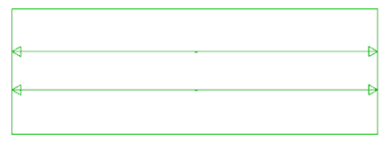
- Stiffener Endcut symbol in Symbolic View:
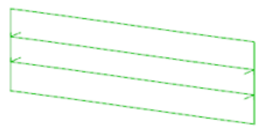
- Stiffener Endcut symbol in Expansion View:
Draw – Use of Grid Ruler in small / narrow Views
The Grid Ruler feature has been enhanced at this release for small or very narrow views so that a user can clearly view the position and the direction of the content.The development ensures that the grid ruler has at least two ticks and at least two labels, so that the position and direction is clear for the identified View.
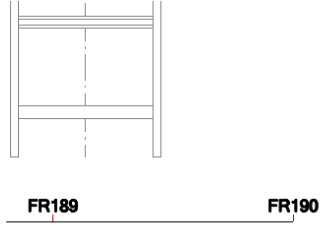
To support this development, a Closing Ticks attribute has been introduced to control the behaviour of the Grid Ruler:
- Display grid ruler first and last tick as long tick with label.
- Off – Long ticks with labels are placed on grid ruler main locations (indicated by long tick index).
- On – Long ticks with labels are placed on grid ruler closing ticks and main locations (indicated by longtick index).
- Auto – Grid ruler displays at least 2 long ticks with labels. Closing ticks are added when necessary ona short grid ruler.
- By Style – Closing ticks defined in grid ruler style.
- When creating grid ruler on narrow views, the ruler length may be automatically extended to includeat least 2 ticks in case when closing ticks property is enabled in grid ruler visual style
Setting View Scale & View Title in Advanced Views forms
Functionality and fields have been implemented to define a View Scale and a View Title when creating Advanced views:
- LLD View creation form.
- Multi LLD View creation form.
- Expansion View creation form.
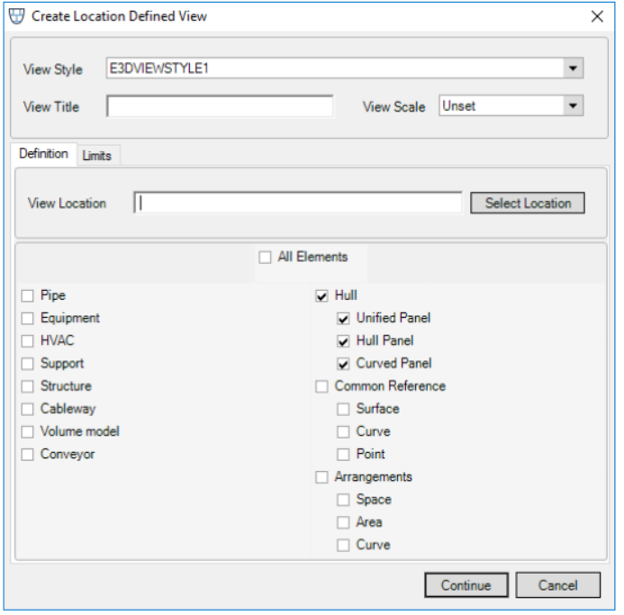
- View Scale
To define a View Scale the user can select the required scale from the available options list.
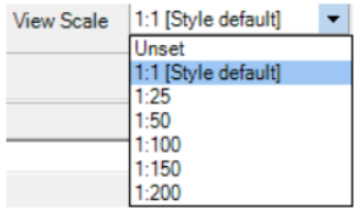
The default value is set to Unset which results in the scale being automatically calculated to the defined frame. If the View Style has a pre-defined scale, this will be used as a default value. All scales derived from a View Style have an additional postfix [Style default].All scale values are Metric and where the View Style pre-defined scale is in another system, it will be automatically converted.The View Scale value will define the size of the view frame (if unset it will not affect the view frame).
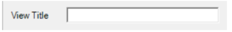
- View Title
To define a View Title the user can enter text within the available text box. The title cannot have more than 1000 characters but can include symbols, numbers and spaces. The View Title can be defined as intelligent or general text under a View. The View Title can subsequently be modified via the Properties Grid where the View is selected.
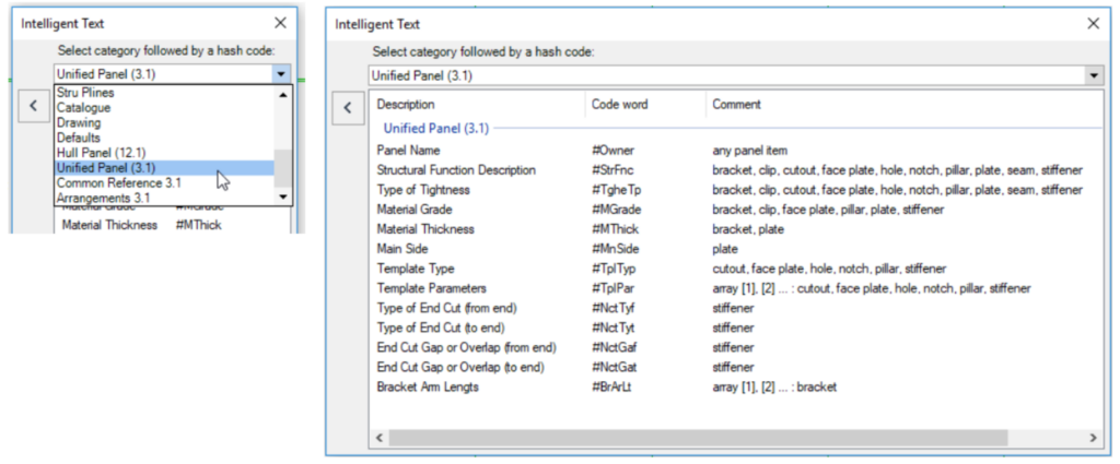
Intelligent texts for (new) Marine elements
A set of intelligent texts suitable for the new hull design models (Common Reference, Arrangements, Upanel) has been introduced at this release
Advanced Labels
This release allows Draw users to efficiently define and add a label to a View with information about an identified element’s position, weight and centre of gravity via an introduced Advanced option in the Annotate group of the ANNOTATE tab.
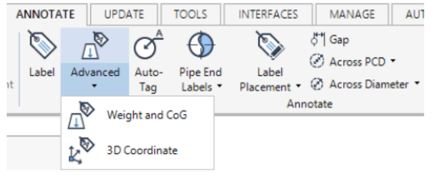
Advanced Labels are generated from introduced special Symbol Templates (SYTM). The default template is set viathe System Defaults and the selection of an Advanced Symbol library where templates are stored.
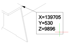
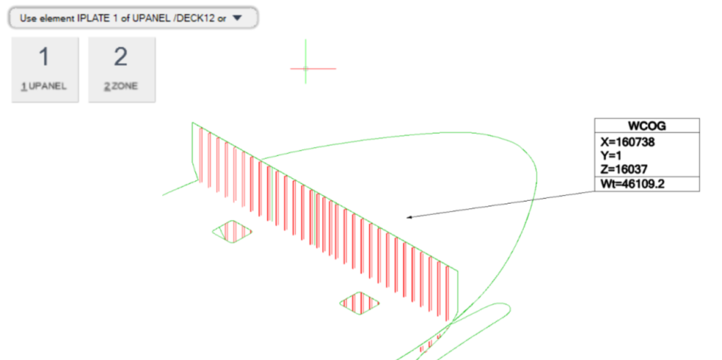
On selecting the template, the user is prompted to select an element from the Model hierarchy to be used. The example output is as follows:
- 3D Coordinate Label:
- Weight & Center of Gravity Label:
Additional Unit format
The use of syntax Ucode Feet USA dist adds a single text quotation mark (‘) as a suffix for foot.
Export lines to DWG from DRAW
The PATNAM attribute on LINEST elements can now be set to OFF to disable the line drawn between glyphs. The default value for PATNAM is SOLID.
Dimension Text Frame
An ability to add a visible text frame to dimensions has been introduced at this release. The functionality is available for all dimension types. The frame properties can be modified via the Dim Text Frame Sides Visibility in the Properties Grid for a dimension or, alternatively, for an individual dimension text via the Vertex Editor.
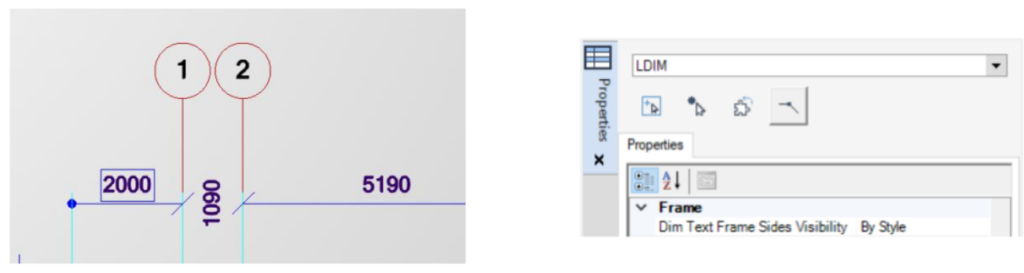
By default, the value in the Dim Text Frame Sides Visibility field is populated By Owner.
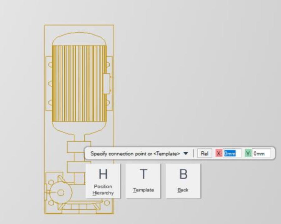
Hierarchy selection for Annotation
When annotating (labelling or dimensioning) a View in Draw by picking an intelligent model element (for example Ppoint, item or owner), a new option Position Hierarchy is now available via the context editor. This option allows a user to select a higher hierarchical element where appropriate e.g. Equipment.
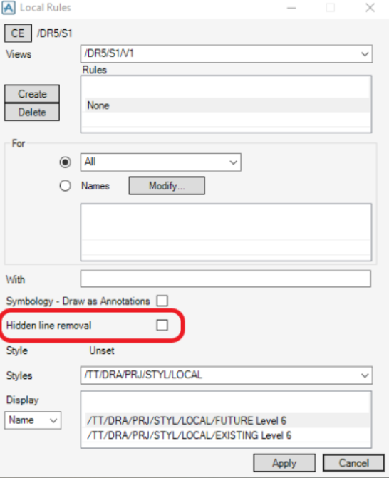
Hidden Line Removal toggle addition to the Local Rules form
A Hidden line removal toggle has been introduced to the Local Rules form to allow the NoHLR flag to be controlled on rule creation.